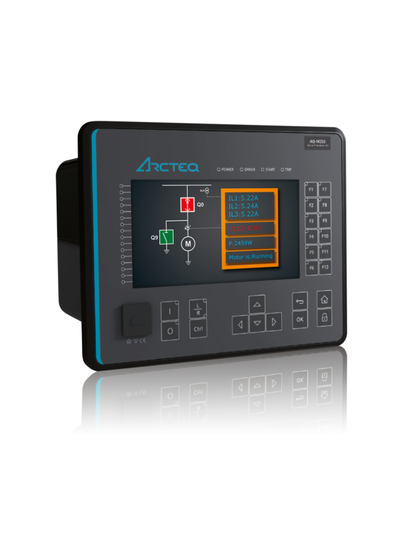
AQ-M255 Motor protection device
Home Protection relays Motor protection & control AQ-M255 Motor protection device
Description
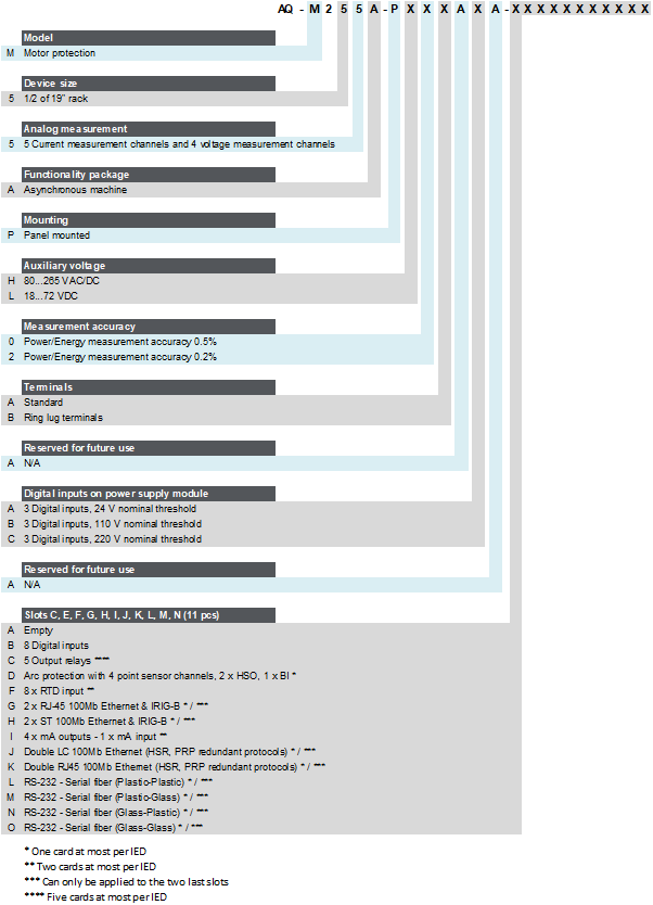
The AQ-M255 motor protection device offers a modular protection and control solution for larger and more important motors that require a large I/O capacity. You can add up to eleven (11) I/O or communication cards into the device for extensive monitoring and control applications. You can also connect up to sixteen (16) RTD signals for thermal alarming and tripping. AQ-M255 communicates using various protocols, including the IEC 61850 substation communication standard.
Highlights:
Powerful motor management with a large I/O capacity.
Five (5) thermal models (time constant accurate).
Soft start protection beginning from 6 Hz.
Wye-delta started motor supervision.
Two-speed motor protection.
Optional power and energy measurement accuracy of up to 0.2 %.
Asynchronous and synchronous motors.
Technical data
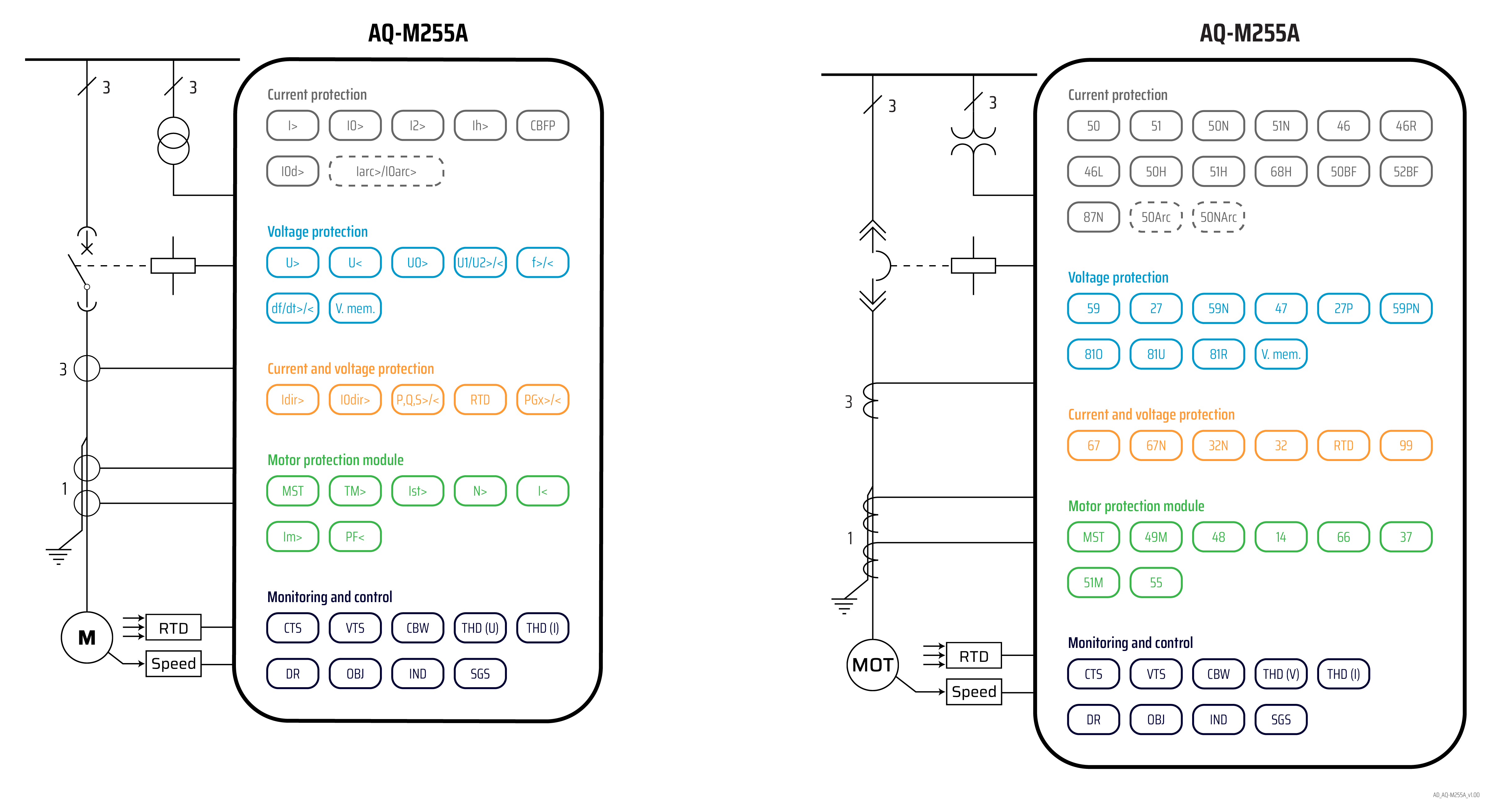
Non-directional overcurrent (I>; 50/51) - 4 stages (INST, DT or IDMT)
Non-directional earth fault (I0>; 50N/51N) - 4 stages (INST, DT or IDMT)
Directional overcurrent (Idir>; 67) - 4 stages (INST, DT or IDMT)
Directional earth fault (I0dir>; 67N/32N) - 4 stages (INST, DT or IDMT)
Negative sequence overcurrent/ Phase current reversal/ Current unbalance (I2>; 46/46R/46L) - 4 stages (INST, DT or IDMT)
Harmonic overcurrent (Ih>; 50H/51H/68H) - 4 stages (INST, DT or IDMT)
Circuit breaker failure protection (CBFP; 50BF/52BF)
High-impedance or low-impedance restricted earth fault/ Cable end differential (I0d>; 87N)
Overvoltage (U>; 59) - 4 stages (INST, DT or IDMT)
Undervoltage (U<; 27) - 4 stages (INST, DT or IDMT)
Neutral overvoltage (U0>; 59N) - 4 stages (INST, DT or IDMT)
Sequence voltage (U1/U2>/<; 47/27P/59PN) - 4 stages (INST, DT or IDMT)
Overfrequency and underfrequency (f>/<; 81O/81U) - 8 stages (INST or DT)
Rate-of-change of frequency (df/dt>/<; 81R) - 1 stage (DT)
Power protection (P, Q, S>/<; 32) - 4 stages (DT)
Resistance temperature detectors (RTD)
Machine thermal overload (TM>; 49M)
Motor status monitoring
Motor start/ Locked rotor monitoring (Ist>; 48/14)
Frequent start (N>; 66)
Non-directional undercurrent (I<; 37)
Mechanical jam (Im>; 51M)
Power factor protection (PF<; 55)
Voltage memory
Programmable stage (PGx>/<; 99)
Arc protection (IArc>/I0Arc>; 50Arc/50NArc) (optional)
Number of objects to control and monitor: 10
Number of indicators to monitor: 10
Number of setting groups: 8
Phase, sequence and residual currents (IL1, IL2, IL3, I01, I02)
Phase, sequence and residual voltages (UL1, UL2, UL3, U12, U23, U31, U0)
Frequency (f)
Power (P, Q, S, pf) and Energy (E+, E-, Eq+, Eq-)
Power and energy class 0.5
Power and energy measurement accuracy of up to 0.2 % (optional)
Current transformer supervision
Voltage transformer supervision (60)
Circuit breaker wear monitoring
Total harmonic distortion (current)
Total harmonic distortion (voltage)
Running hour counter
Measurement recorder
Measurement value recorder
Event recorder (max. 15 000 permanent event records)
Disturbance recorder (max. 100 records á 5 seconds at 3.2 kHz sampling)
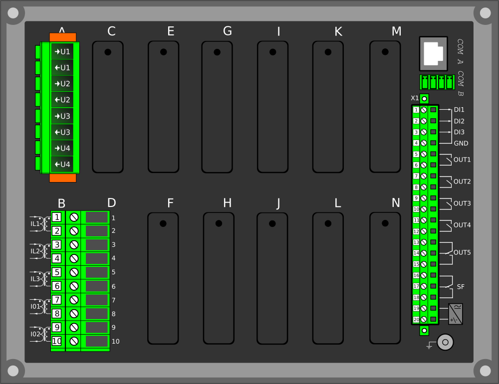
Current inputs: 5
Voltage inputs: 4
Digital inputs (fixed): 3
Digital outputs (fixed): 5
Number of empty slots: 11
Digital inputs: +8/16/24/32/40/48/56/64/72/80/88 (optional)
Digital outputs: +5/10/15/20/25/30 (optional)
Milliampere I/O module (4 mA outputs + 1 mA input) (optional)
Arc protection module (4 sensors + 2 HSO + 1 BI) (optional)
Communication media (see "Communication" below)
External I/O modules (see "Accessories" below)
Communication inputs
RJ-45 100 Mbps Ethernet (front panel, fixed)
RJ-45 100 Mbps Ethernet and RS-485 (rear panel, fixed)
Double RJ-45 Ethernet & IRIG-B communication module (optional)
Double ST Ethernet & IRIG-B communication module (optional)
Double LC (HSR/PRP) Ethernet communication module (optional)
RS-232 & serial fiber communication module (optional)
Communication protocols
IEC 61850 (edition 1)
IEC 61850 (edition 2)
IEC 60870-5-101/104
IEC 60870-5-103
Modbus/RTU and Modbus/TCP
DNP3
SPA
AX007 External 6-channel 2-/3-wire RTD input module (pre-configured)
AX008 External 8-channel thermocouple and mA input module (pre-configured)
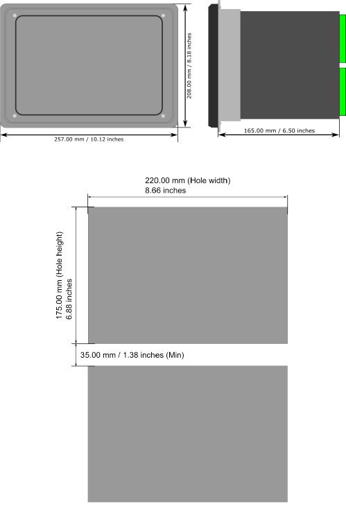
AX013 Raising frame (120 mm)
AX014 Raising frame (40 mm)
AX015 Wall mounting bracket
Download
AQ 200 series flyer, v2.01 (English)
AQ 200 series flyer, v2.01 (Finnish)
AQ 200 series flyer, v2.01 (Swedish)
AQ 200 series product catalog (ANSI, v2.03, EN, September 2024)
AQ 200 series product catalog (IEC, v2.03, EN, September 2024)
AQtivate PRO flyer, v1.00 (English)
AQtivate PRO flyer, v1.00 (Finnish)